 Configuring Actions
Use the Actions view to setup tasks for the drive to perform based on selected sources and conditions. Up to 32 actions can be configured.
Each action, at a minimum, has a source (ACTIONx.SOURCE), a condition (ACTIONx.CONDITION), and a task (ACTIONx.TASK). For example, action 1 below will attempt to Enable Axis 1 any time it sees a rising edgeA rising edge is the transition of a digital signal from low to high. It is also called positive edge on Digital Input 1. This action also has a source id (ACTION.SOURCEID) setting which digital input to react on, and a task id (ACTION.TASKID) setting which axis to enable.
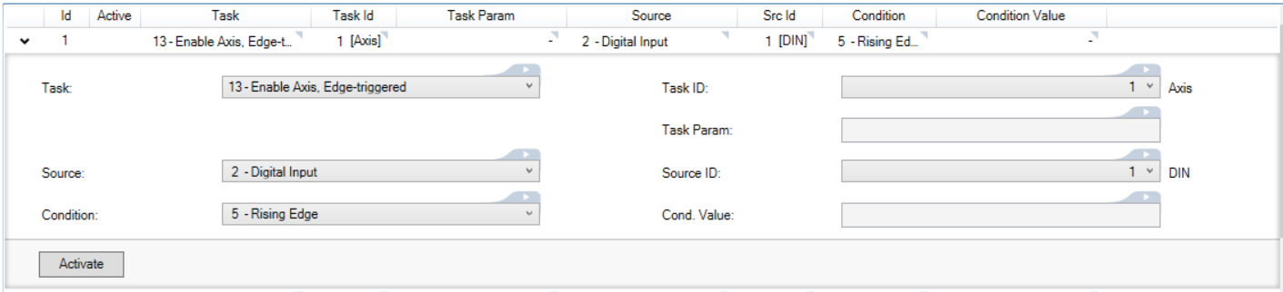
An action can also have a condition value (ACTIONx.CONDITIONVALUE) and a task parameter (ACTIONx.TASKPARAM).
A condition value is required when the condition performs a comparison. For example, if the action source is set to Analog Input, and the condition is set to "Falls Below Threshold", a condition value will define the threshold. If the condition value is set to 4.5, the action will check if the analog input transitions from a value greater than 4.5 volts to a value less than 4.5 volts.

Some tasks require task parameters to further specify what is acted on. For example, if the task is Motion Task, Edge-triggered the task parameter field will appear. Setting this field to 5 specifies that the action will start motion task 5 on the selected axis.

Action Execution
Actions are executed sequentially, top to bottom, starting at Action 1, at a 4kHz rate.
Certain tasks, like clearing faults, may take a longer than 4kHz cycle to execute. These tasks will be initiated in a low priority thread. If the task is triggered a second time while the task is already running, it will not be queued to run again, and the action will be ignored until the running task is complete.
Scanning of the table does not begin until boot up has completed. Any edges which occur on any signal will be ignored until this time. In addition, edge triggered actions will not be executed if the test condition is already true at boot time.
To avoid inconsistent behavior, an action will automatically be disabled when any of its fields are edited. Reactivate the action after editing any of its field settings.
Action Sources
The action source is the input the drive reacts on. The following is a list of available actions:
| Value | Description |
|---|---|
| 0 | No source |
| 1 | Mains ready |
| 2 | Digital Input |
| 3 | Digital Dio (Bidirectional) |
| 4 | Actual Velocity |
| 5 | Axis Faulted |
| 6 | Home Complete |
| 7 | Motion Task in Position |
| 8 | Controlled Stop Active |
| 9 | Software Limit |
| 10 | Move Complete |
| 11 | Position Error, Absolute |
| 12 | Axis Enabled |
| 13 | Analog Input |
| 14 | Current Command |
| 15 | Velocity Error |
| 16 | Velocity Command |
| 17 | Position Feedback |
| 18 | Axis Disable Immediately |
| 19 | Brake State |
| 20 | Ready to Operate (RTO/BTB) |
Action Tasks
An action task defines the drive function to execute when the source's condition is met. Some tasks will execute a drive function when the condition becomes true. Other tasks will execute every cycle and use the condition or source to set a drive value.
| Value | Description |
|---|---|
| 0 | No task |
| 1 | Digital Output from Source, Continuous |
| 2 | Set Digital Output, Edge-triggered |
| 3 | Clear Digital Output, Edge-triggered |
| 5 | Motion Task, Edge-triggered |
| 6 | Home Task, Edge-triggered. Homes based on the saved parameters on the drive |
| 7 | Stop, Edge-triggered |
| 8 | Start Jog, Edge-triggered |
| 9 | Controlled stop, then disable with re-enable. Drive disables but SW disable bit is not set. If an active Task is disabled (or deactivated) CS bit is cleared and the drive is enabled. |
| 10 | Controlled stop, then disable. Drive disables and SW disable bit is set. If an active Task is disabled (or deactivated) CS bit is cleared but the SW bit remains set and the drive remains disabled. |
| 11 | Controlled stop, and stay enabled. Implemented with suspend motion. Drive remains enabled while motion stops. CS bit is not set. |
| 12 | Clear Faults, Edge-triggered |
| 13 | Enable Axis, Edge-triggered |
| 15 | Set Analog Output |
| 15 | Set Analog Output from Source |
| 16 | Disable Axis, Edge-triggered |
| 18 | Activate Gearing, Edge-triggered |
| 19 | Add Gearing Position, Edge-triggered |
| 20 | Set Motion Task Feedrate |
| 21 | Digital DIO From Source, Continuous |
| 22 | Set Digital DIO, Edge-triggered |
| 23 | Clear Digital DIO, Edge-triggered |
Chaining Actions
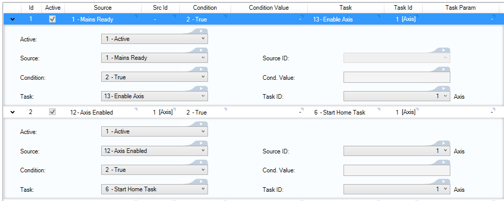
Actions are executed sequentially, so they can be configured to execute a chain of actions.
For example, if Action 1 enables axis 1 when mains ready is true, then Action 2 can be configured to start homing when axis 1 is enabled. When Action 1 completes its task, it will trigger Action 2 to execute as well.
|
Stay Connected with Kollmorgen       
|
Copyright © 2018 Kollmorgen |

|